
-
-
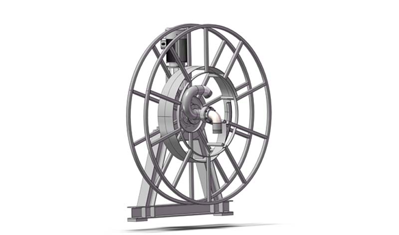
A Winding Device with A Pneumatic Brake
Abstract:A winding device with a pneumatic brake includes reel assembly machinery, power deceleration machinery, rotary joint assembly mechanism, braking mechanism through pneumatic control, torque limit and travel limit protection mechanism, pneumatic control components and electrical control mechanism. The utility model is an electric winding device which can effectively compress the product size by adjusting the air pressure and adjusting the braking torque. According to the working characteristics of the shield machine, when the winding device retracts the cable, the motor is powered on and drives the reel to drag the water pipe from the ground into the reel. When the winding device conducts cable laying, the motor loses power, and the water pipe is dragged out from the reel to the effective distance by external force. At this time, the air pressure can be adjusted by 0-0.8MPa, and the friction torque of the brake can be adjusted to easily drag the water pipe out. The utility model greatly meets the demand of the shield machine market, can comprehensively replace similar foreign products, and has the advantage that it is cost-effective. Technical Field:The utility model relates to the winding device for a shield machine, in particular to the winding device with a pneumatic brake. Background Art:With the continuously growing demand and high-end of China's mechanical equipment industry, so far, China's urban subway projects have an increasing demand for shield machines. Domestic shield machines have broken through foreign monopoly and most of them have been localized. Corresponding domestic manufacturers also have substitutes of the supporting water pipe drum. However, according to the actual working conditions of the shield machine, the water pipe drum with pneumatic control cable laying is still from foreign countries. The domestic manufacturers use the hysteresis water pipe drum instead. When the diameter of the water pipe is too large and the coiling length is too long, the coiling torque of the hysteresis water pipe drum is often insufficient. The product size is too large, which may be easily limited by the installation space of shield machine, which restricts the development of products. Effect:The utility model is a winding device with a pneumatic brake, which is an electric winding device which can effectively compress the product size by adjusting the air pressure and adjusting the braking torque. According to the working characteristics of the shield machine, when the winding device retracts the cable, the motor is powered on and drives the reel to drag the water pipe from the ground into the reel. When the winding device conducts cable laying, the motor loses power, and the water pipe is dragged out from the reel to the effective distance by external force. At this time, the air pressure can be adjusted by 0-0.8MPa, and the friction torque of the brake can be adjusted to easily drag the water pipe out. The utility model greatly meets the demand of the shield machine market, can comprehensively replace similar foreign products, and has the advantage that it is cost-effective....
-
-
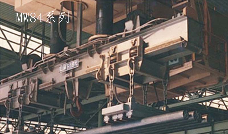
Utility Model Patent: A Lifting Electromagnet for Handling Bundled Steel Plates
AbstractA lifting electromagnet for handling bundled steel plates comprises a lifting mechanism, a magnetic pole mechanism and a cable lead-out mechanism. The mentioned magnetic pole mechanism is composed of a square magnetic pole, a coil housing, hexagon socket bolts, coils, iron cores and filler. There are two iron cores, which are arranged symmetrically on the left and right, and the outside of each iron core is wound with a coil. The outside of the mentioned coil is surrounded by a coil housing, and a layer of filler is arranged between the coil and the coil housing and fixed with insulating tape. The mentioned square magnetic pole is installed at the bottom of each iron core with hexagon bolts. The electromagnet of the utility model is specially used for safely lifting and transporting bundled steel plates, which is specially developed for the special form of bundled steel plates, and has strong magnetic permeability and attraction. Technical FieldThe utility model relates to a lifting electromagnet, in particular to a lifting electromagnet used for handling bundled steel plates. Background ArtAt present, in the field of lifting and handling, the structure of the lifting electromagnet used for handling bundled steel plates is not reasonable, resulting in too small attraction force of the electromagnet, insufficient magnetic permeability and short service life. The defects are as follows:1. The magnetic conductivity and processability of magnetic materials are very poor, resulting in weak magnetic permeability and attraction;2. The insulation and heat resistance of the coil are poor;3. Single-coil structure, with small magnetic field strength, unsuitable for handling bundled steel plates requiring deep magnetic permeability;4. The waterproof performance of the open structure is very poor. ContentsThe technical problem to be solved by the utility model is to provide a lifting electromagnet for handling bundled steel plates to solve the problems in the mentioned background art.The utility model solves the technical problems by adopting the following technical solutions:The lifting electromagnet for handling bundled steel plates comprises a lifting mechanism, a magnetic pole mechanism and a cable lead-out mechanism,The mentioned magnetic pole mechanism is composed of a square magnetic pole, a coil housing, hexagon socket bolts, coils, iron cores and filler. There are two iron cores, which are arranged symmetrically on the left and right, and the outside of each iron core is wound with a coil. The outside of the mentioned coil is surrounded by a coil housing, and a layer of filler is arranged between the coil and the coil housing and fixed with insulating tape. The mentioned square magnetic pole is installed at the bottom of each iron core with hexagon bolts;The mentioned lifting mechanism is composed of a top cover, a chain and hexagonal bolts. The top cover is connected with the upper end of the iron core by hexagonal bolts to close the upper part of the coil. Four lifting lugs are welded on the upper surface of the top cover, and four chains are respectively fixed on the lifting lugs to form a general hook. During use, the user equipment can hook the general hook to lift the electromagnet for operation;The cable lead-out mechanism comprises a junction box, which is arranged on the top cover and leads out the positive and negative cables of the coil.In this utility model, the coil is the SBEB-30/180 coil.By adopting the structure above, the utility model has the following beneficial effects:The electromagnet of the utility model is specially used for safely lifting and transporting bundled steel plates, which is specially developed for the special form of bundled steel plates, and has strong magnetic permeability and attraction. Its characteristics are as follows:1. Better magnetic conductivity with double iron cores.2. The coil is fixed with insulating tape, with excellent insulation and heat resistance.3. Double-coil structure, with large magnetic field strength, suitable for the occasions that require deep magnetic permeability for handling.4. Fully sealed structure with good waterproof performance.5. Good heat dissipation and heat insulation, safe and reliable, with long service life.Yueyang Credsun Electric Co., Ltd. will serve you with excellent products being the base, high-quality service being the core and honest operation being the principle! Extracted from the official website of Yueyang Credsun Electric Co., Ltd.: http://www.credsun.com...
-
-
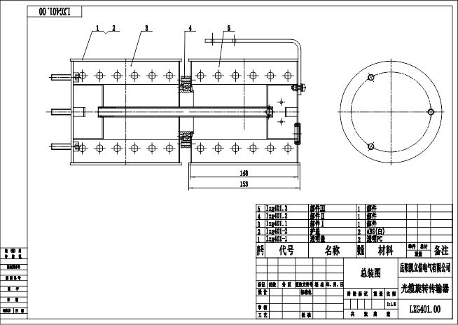
Optical Fiber Rotary Connection Device
Abstract:Optical fiber rotary connection device comprises a fixed connecting mechanism for rotary connection device, a reduction mechanism for rotary connection device, an optical fiber rotary connection mechanism, and a disc rolling support mechanism for rotary connection device. For the mentioned optical fiber rotary connection mechanism, the optical fiber is connected into the planetary wheel shaft through the fixed connecting mechanism for rotary connection device. The optical fiber is tightly wound on the optical fiber satellite rotating wheel with certain pitch and semicircular thread. After a certain number of turns, it is wound reversely on the rotating wheel of the optical fiber satellite and enters the satellite wheel shaft. The tail end is fastened with metal gland, the optical fiber is fixed on the base plate of the optical fiber junction box after reserving a suitable length, and then connected to the optical fiber terminal box. The user's optical fiber enters the optical fiber terminal box to realize the transmission of optical fiber signal. The utility model can realize the transmission of signals of 12-core and above multimode/single-mode optical fiber without interference, and has the advantages of safety, reliability, maintenance free and low cost. Technical Field:The utility model relates to a cable connection device, in particular to an optical fiber rotary connection device. Background art: With the continuously growing demand and high-end of China's mechanical equipment industry, so far, optical fiber rotary connection device is an essential device for the connection of various optical devices and modules in optical fiber communication system. The demand for optical fiber rotary connection is increasing. Domestic products have achieved a breakthrough in 6-core optical fiber rotary connection devices, and several companies have the ability to conduct mass production. However, for the rotary optical fiber connection device with 12 cores and above, the original design mode can not make a breakthrough in optical fiber processing, which greatly restricts the wide application of products, and similar products must rely on imports. Therefore, according to the market demand, it is urgent to solve the above problems by creating another design mode according to the market demand. Contents:The utility model aims to provide an optical fiber rotary connection device which can realize the transmission of signals of 12-core and above multimode/single-mode optical fiber without interference.The contents of the utility model is realized through the following technical solutions:The optical fiber rotary connection device comprises a fixed connecting mechanism for rotary connection device, a reduction mechanism for rotary connection device, an optical fiber rotary connection mechanism and a disc rolling support mechanism for rotary connection device. The mentioned fixed connecting mechanism for rotary connection device comprises an optical fiber box, a mounting base, fork nuts, hexagon bolts, a flange plate and a standard flat key. The mentioned reduction mechanism of the rotary connection device comprises a variable speed gear set, a transmission gear set and a deep groove ball bearing. The optical fiber rotary connection mechanism comprises a disc shaft sleeve, an adjusting gasket, a satellite wheel shaft, a slotted set screw with long dog point, and an optical fiber satellite rotating wheel. Satellite wheel tension spring, satellite gear, hexagon socket cap screw, high-quality metal gland, planetary gear, standard flat key, right rotating disc, planetary wheel shaft, counterweight bar, optical fiber planetary rotating wheel, planetary wheel tension spring, hexagon nut, left corner nut, left rotating disc and hexagon socket cap screw. The connecting relationship between all the parts including the disc roller assembly of the mentioned disc rolling support mechanism for rotary connection device is: The mentioned optical fiber rotary connection device is installed at the tail of the main shaft of the optical cable drum; The side of the mentioned mounting base is fixed on the front plate of the optical fiber junction box through hexagon bolts; The fork nut is fixed on the main shaft of the optical cable drum, but it is not connected with the bolt on the optical fiber junction box of the optical fiber rotary connection device; The fork nut is connected with the main shaft through the flat key; The transmission gear set is connected with the planetary wheel shaft through the disc shaft sleeve; Two groups of bolts are installed on the transmission gear in the transmission gear set, which are fixed on the right rotating disc and the left rotating disc; The inner left side plate of the optical fiber planetary rotating wheel is fixedly connected with one side of the planetary wheel tension spring through bolts; The other side of the planetary wheel tension spring is fixed on the planetary wheel shaft with bolts; The internal structure of the optical fiber satellite rotating wheel is the same as that of the optical fiber planetary rotating wheel, and the tension spring of the satellite wheel is installed on the other side.The mentioned fixed connecting mechanism for rotary connection device fixes the rotary connection device in the optical fiber junction box of the optical cable drum, and uses fork nuts to connect the transmission main shaft of the drum with the rotary connection device, so that the rotary connection device can work normallyFor the mentioned optical fiber rotary connection mechanism, the optical fiber is connected into the planet gear shaft through the fixed connecting mechanism for rotary connection device. The optical fiber is tightly wound on the optical fiber planetary rotating wheel with certain pitch and semicircular thread. After a certain number of turns, it is wound reversely on the rotating wheel of the optical fiber satellite, enters the satellite wheel, and then enters satellite wheel shaft. The tail end is fastened with metal gland, the optical fiber is fixed on the base plate of the optical fiber junction box after reserving a suitable length, and then connected to the optical fiber terminal box. The user's optical fiber enters the optical fiber terminal box to realize the transmission of optical fiber signal.For the mentioned disc rolling support mechanism for rotary connection device: since the optical fiber rotary connection mechanism is suspended for a long time and preventing its deformation, the support mechanism is hereby designed, and the mechanism is independently fixed at the appropriate position at the bottom of the optical fiber box to contact the disc.The utility model has the following beneficial effects:The optical fiber planetary rotating wheel of the utility model always rotates synchronously with the main shaft of the optical cable drum. The optical fiber satellite rotating wheel always makes a circular motion around the optical fiber planetary rotating wheel, but does not revolve on its own axis, which solves the problem of rotation and distortion of the optical fiber at the other end, so that the signal of the optical fiber can be transmitted normally without interference. At the same time, through the action of the reduction gear, the optical fiber can be wound more turns, the length of the optical fiber planetary rotating wheel and the optical fiber satellite rotating wheel is effectively reduced, and the universality of adapting to working conditions is increased. The utility model can realize the transmission of signals of 12-core and above multimode/single-mode optical fiber without interference, and has the advantages of safety, reliability, maintenance free and low cost....
-
-
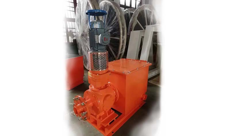
A Manufacturing Method of Automatic Winding and Unwinding Device for Flameproof Cable Drum
Patent: A Manufacturing method of automatic winding and unwinding device for flameproof cable drumTechnical Field: The present invention involves a technology for winding and unwinding cables in coal mine equipment, in particular to an automatic winding and unwinding device for flameproof cable drums.Background Art: With the continuous improvement of mechanization degree of coal mine equipment, large-scale electric traction mobile equipment (such as roadheader, continuous miner, shuttle car, etc.) is more and more widely used in coal mines because of its advantages of energy saving, environmental protection and high integrated control degree. Since the towed cable structure is used, the running speed and maximum running distance of these equipment are severely restricted by the performance of cable drum. Mine cable has high voltage (1140V) and there are flameproof requirements to it, and its overall size and weight are very large. Motor drive and electric control are generally used for the traditional cable automatic winding mechanism, and there is no flameproof mechanism in the lead-in and lead-out position of the cable. However, due to the high air humidity in the coal mine and the existence of explosive gases such as methane, the traditional motor drive and electric control can not be directly applied in the coal mine.Contents:The technical problem to be solved by the invention is to propose an automatic winding and unwinding device for flameproof cable drums aim at the shortcomings of the prior art, which can increase the moving distance of equipment, speed up the moving speed of equipment, reduce the workload of miners and improve the working efficiency of equipment. The technical problem to be solved by the invention is realized by the following technical scheme: an automatic winding and unwinding device for flameproof cable drums, comprising a cable drum hydraulic motor, an oil supply pipe and an oil return pipe of the cable drum hydraulic motor, featuring an overflow control system installed between the oil supply pipe and the oil return pipe. The overflow control system consists of a hydraulic control reversing valve and a one-way valve installed on the oil supply pipe, and the oil inlet side of the one-way valve is provided with a winding control oil circuit and an oil drain pipe connected with the oil return pipe. The winding control oil circuit is provided with a high-pressure relief valve, the oil outlet side of the one-way valve is provided with an unwinding control oil circuit connected with the oil return pipe, the unwinding control oil circuit is provided with a low pressure-relief valve, the winding control oil circuit is connected with the winding control position of the hydraulic control reversing valve, the oil drain pipe and the unwinding control oil circuit are connected with the unwinding control position of the hydraulic control reversing valve, and the oil inlet of the hydraulic control reversing valve is connected with the oil supply pipe at the oil outlet side of the one-way valve. The technical problem to be solved by the invention can be further realized by the following technical scheme: a parking brake circuit is arranged between the oil supply pipe and the oil return pipe in the front of the overflow control system, and a hydraulic control one-way valve is arranged on the parking brake circuit. The technical problem to be solved by the invention can be further realized by the following technical scheme: an adjustable throttle circuit and an overhaul circuit are installed between the oil supply pipe and the oil return pipe at the rear of the overflow control system, the adjustable throttle circuit is provided with a throttle valve that can adjust the oil quantity, and the overhaul circuit is provided with a high-pressure ball valve. When winding the cable, the winding control oil circuit is in working state, hydraulic oil enters the hydraulic motor of the cable drum through the one-way valve, and the hydraulic motor drives the cable drum to rotate by feeding oil forward, thus winding the cable. At this time, the oil supply pressure of the hydraulic motor (i.e., the winding torque) is set by the high-pressure relief valve, and when the set pressure value is exceeded, the high-pressure relief valve will realize the pressure relief of overflow. When unwinding the cable, the cable is pulled out of the drum by the traction of the shuttle car, which makes the hydraulic motor rotate in the reverse direction and work in the mode of hydraulic pump. The pressure of the oil supply pipe at the oil outlet side of the one-way valve rises, which makes the hydraulic control reversing valve move to the unwinding control position. At this time, the pressure oil directly returns to the oil tank through the oil drain pipe, and the high-pressure oil discharged from the hydraulic motor goes to the oil return tank through the unwinding control oil circuit, and the low-pressure relief valve controls the oil return pressure. When the equipment is stationary and in the parking brake state, the hydraulic control one-way valve controlled by the pressure of the parking brake system is opened, and the oil supplied by the oil pump directly returns to the oil tank without passing the control valve block, which can greatly reduce the working load of the pump and the system calorific value. Compared with the prior art, the positive and negative rotation of the hydraulic motor is automatically controlled through the overflow of the high-pressure relief valve and the low-pressure relief valve under the set pressure in this invention, thereby realizing the automatic winding and unwinding of the cable. The cable drum automatic winding and unwinding device can be widely used in various underground electric traction devices in coal mines. By realizing automatic winding and unwinding of cables on flameproof cable drums, automatic pressure relief, buffering and shock absorption, overload protection, and cable full winding and unwinding protection, it can effectively increase the running distance of the devices, improve the running speed of the devices, simplify the operation procedures, reduce the workload of miners, improve the working efficiency of the devices, greatly promote the wide application of large-scale electric traction mobile devices in coal mines, and improve the localization speed, thus it features great economic and social benefits. The hydraulic principle diagram of the present invention is shown in Fig. 1.Detailed description of the invention: An automatic winding and unwinding device for flameproof cable drum, comprising a cable drum hydraulic motor 7, an oil supply pipe 11 and an oil return pipe 1 of the cable drum hydraulic motor 7. The oil supply pipe 11 is connected with a gear pump, the oil return pipe 1 is connected with an oil return tank, an overflow control system 12 is installed between the oil supply pipe 11 and the oil return pipe 1. The overflow control system 12 includes a hydraulic control reversing valve 14 and a one-way valve 13 installed on the oil supply pipe. On the oil inlet side of one-way valve 13, there are winding control oil circuit 2 and oil drain pipe 3 which are connected with the oil return pipe. The winding control oil circuit 2 is provided with a high-pressure relief valve 9, while the oil outlet side of one-way valve 13 is provided with an unwinding control oil circuit 4 which is equipped with a low-pressure relief valve 8. The winding control oil circuit 2 is connected to the winding control position of the hydraulic control reversing valve 14, and the oil drain circuit 3 and the unwinding control oil circuit 4 are connected to the unwinding control position of the hydraulic control reversing valve 14. The oil inlet of the hydraulic control reversing valve 14 is connected with the oil supply pipe on the oil outlet of the one-way valve. A parking brake circuit is designed between the oil supply pipe and the oil return pipe in the front of the overflow control system 12, and a hydraulic control one-way valve 10 is installed on the parking brake circuit. An adjustable throttle circuit and an overhaul circuit are installed between the oil supply pipe and the oil return pipe at the rear of the overflow control system 12. The adjustable throttle circuit is equipped with a throttle valve 5 with adjustable oil quantity and the overhaul circuit is equipped with a high-pressure ball valve 6. Oil is supplied by a gear pump with a flow rate of 21.71L/Min, which is one of the triple pumps, and its main function is to control the automatic winding and unwinding of cables. The working principle is that the positive and negative rotation of the hydraulic motor is automatically controlled through the overflow of the high-pressure relief valve and the low-pressure relief valve under the set pressure in this invention, thereby realizing the automatic winding and unwinding of the cable. The working process is as follows: When the shuttle car runs in the direction of power supply, that is, when the cable is wound up, the hydraulic control reversing valve is in the left winding control position under the action of the reset spring, and the pressure oil output by the gear pump enters the hydraulic motor of the cable drum through the one-way valve, and the hydraulic motor drives the cable drum to rotate by feeding oil in the forward direction, so as to wind up the cable. At this time, the oil supply pressure of the hydraulic motor (i.e., the winding torque) is set by the high-pressure relief valve, and the pressure value is set according to the cable parameters of the shuttle car and the hanging angle of the cable when the equipment is under operation. When the shuttle car runs away from the power supply, that is, when the cable is unwound, the cable is pulled out from the drum under the action of the traction force of the shuttle car, which makes the hydraulic motor rotate reversely and work in the mode of hydraulic pump. The one-way valve is closed, which makes the pressure of the oil inlet controlled by the hydraulic control reversing valve increase, and the valve core is reversed under the action of the reverse control pressure. At this time, the oil discharged from the oil pump directly returns to the oil tank through the reversing valve and the oil drain pipe, and the high-pressure oil discharged from the hydraulic motor returns to the oil tank through the low-pressure relief valve, and only a part of the oil participates in circulation of oil supply of the motor. Set the pressure of the low-pressure relief valve according to the cable parameters (weight and tensile strength, etc.). When the equipment is stationary and in the parking brake state, the hydraulic control one-way valve controlled by the pressure of the parking brake system is opened, and the oil supplied by the gear pump directly returns to the oil tank without passing the overflow control system, which can greatly reduce the working load of the pump and the system calorific value. The throttle valve with adjustable oil quantity can adjust the flow according to different cable types, and at the same time buffer the impact torque of the motor when winding the cable. The high-pressure ball valve opens when the cable drum has fault or is installed for the first time, which can realize the free rotation of the cable drum. The high-pressure overflow condition is when the shuttle car is not moving and the parking brake is not executed, and when the shuttle car is driving in the direction of power supply (i.e. the cable winding state); The low-pressure overflow condition is when the shuttle car runs away from the power supply (i.e. the cable unwinding state); The working condition of the hydraulic control one-way valve is when the equipment is under parking brake; The opening conditions of high-pressure ball valve is when the oil pump motor shuts off and the cable drum needs to rotate freely.Claims:1. An automatic winding and unwinding device for flameproof cable drums, comprising a cable drum hydraulic motor, an oil supply pipe and an oil return pipe of the cable drum hydraulic motor, featuring an overflow control system installed between the oil supply pipe and the oil return pipe. The overflow control system consists of a hydraulic control reversing valve and a one-way valve installed on the oil supply pipe, and the oil inlet side of the one-way valve is provided with a winding control oil circuit and an oil drain pipe connected with the oil return pipe. The winding control oil circuit is provided with a high-pressure relief valve, the oil outlet side of the one-way valve is provided with an unwinding control oil circuit connected with the oil return pipe, the unwinding control oil circuit is provided with a low pressure-relief valve, the winding control oil circuit is connected with the winding control position of the hydraulic control reversing valve, the oil drain pipe and the unwinding control oil circuit are connected with the unwinding control position of the hydraulic control reversing valve, and the oil inlet of the hydraulic control reversing valve is connected with the oil supply pipe at the oil outlet side of the one-way valve.2. According to the automatic winding and unwinding device for flameproof cable drums in Claim 1, a parking brake circuit is arranged between the oil supply pipe and the oil return pipe in the front of the overflow control system, and a hydraulic control one-way valve is arranged on the parking brake circuit.3. According to the automatic winding and unwinding device for flameproof cable drums in Claim 1, an adjustable throttle circuit and an overhaul circuit are installed between the oil supply pipe and the oil return pipe at the rear of the overflow control system, the adjustable throttle circuit is provided with a throttle valve that can adjust the oil quantity, and the overhaul circuit is provided with a high-pressure ball valve.Abstract:An automatic winding and unwinding device for flameproof cable drums, comprising a cable drum hydraulic motor, an oil supply pipe and an oil return pipe of the cable drum hydraulic motor. An overflow control system is installed between the oil supply pipe and the oil return pipe. The overflow control system consists of a hydraulic control reversing valve and a one-way valve installed on the oil supply pipe, and the oil inlet side of the one-way valve is provided with a winding control oil circuit and an oil drain pipe connected with the oil return pipe. The winding control oil circuit is provided with a high-pressure relief valve, the oil outlet side of the one-way valve is provided with an unwinding control oil circuit connected with the oil return pipe, the unwinding control oil circuit is provided with a low pressure-relief valve, the winding control oil circuit is connected with the winding control position of the hydraulic control reversing valve, the oil drain pipe and the unwinding control oil circuit are connected with the unwinding control position of the hydraulic control reversing valve, and the oil inlet of the hydraulic control reversing valve is connected with the oil supply pipe at the oil outlet side of the one-way valve. Automatic winding and unwinding of cables, automatic pressure relief, buffering and shock absorption, overload protection are realized, which can effectively increase the running distance of equipment, improve the running speed of equipment and improve the working efficiency of equipment....
-
-
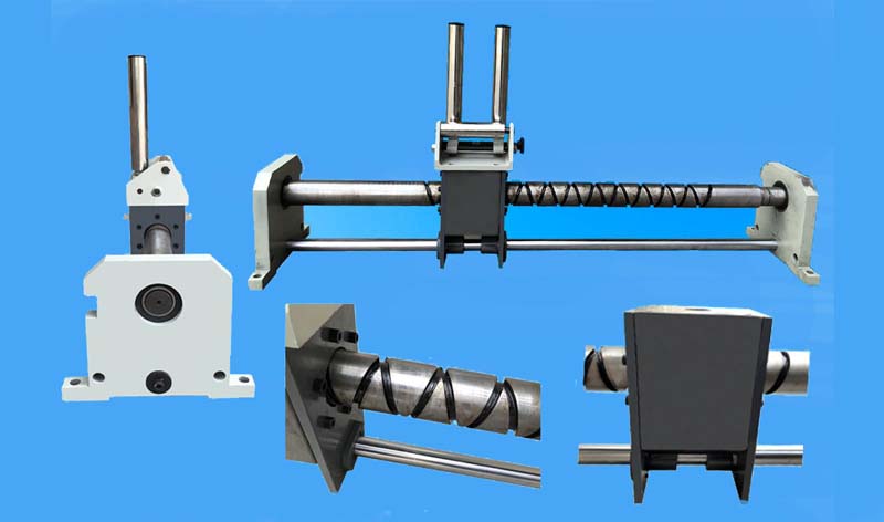
Cable Arrangement Device for the Cable Drum
Abstract:For the cable arrangement device for cable drum: The mentioned cable drum is connected with a motor and a reducer for the power of the main shaft; The mentioned cable arrangement device is arranged at the upstream position of the retracting direction of the cable drum; The mentioned cable arrangement device comprises a cable guiding machine and a cable arrangement mechanism; The cable guiding machine is arranged at the upstream position of the retracting direction of the cable arranging mechanism; The cable arrangement mechanism is equipped with a driving mechanism for providing power. The utility model has a simple structure and greatly improves the winding and unwinding efficiency of cables. At the same time, the cable can be neatly wound on the cable drum, which increases the winding amount of cables. Technical Field:The utility model relates to a cable arrangement device, in particular to a cable arrangement device used on a cable drum. Background Art:With the rapid development of the mechanical device industry in China, large-scale mobile power supply equipment is more and more widely used, and the service length of cables is also increased accordingly. When arranging long-distance cables, the cable drum is generally used, and the cables can be wound and arranged on the cable drum in layers. However, at present, there is no special cable arrangement device for the cable drum, which makes the cable tangled during winding, which not only affects the speed of winding and unwinding cables, but also affects the total winding amount of cables on the cable drum. Contents:The technical problem to be solved by the utility model is to provide a cable arrangement device for the cable drum, which has a simple structure and improves the efficiency, solving the problems in the mentioned background art.The utility model solves the technical problems by adopting the following technical solutions:For the cable arrangement device for cable drum: The mentioned cable drum is connected with a motor and a reducer for the power of the main shaft; The mentioned cable arrangement device is arranged at the upstream position of the retracting direction of the cable drum. The characteristics are: The mentioned cable arrangement device comprises a cable guiding mechanism and a cable arrangement mechanism; The cable guiding machine is arranged at the upstream position of the retracting direction of the cable arranging mechanism; The cable arrangement mechanism is equipped with a driving mechanism for providing power.As an improvement, the internal equipment of the mentioned cable guiding mechanism is provided with a channel for the passage of cables, and the equipment is provided with an over-tension protection cable guiding rack, which is a device for running, arrangement, coiling, winding and unwinding and protection of cables.As an improvement, the cable arrangement mechanism comprises a cable arrangement seat arranged on the chain and capable of reciprocating motion.As an improvement, the mentioned driving mechanism comprises a driving sprocket of the chain, which is chained with the sprocket on the main shaft of the cable drum through a worm gear deceleration mechanism. The structure passes the capacity of the cable drum through the worm gear deceleration mechanism and is equipped with an appropriate reduction ratio to make it suitable for the running of cables with different diameters and reversing transmission.As a further improvement, the chain is provided with a linkage pin shaft mechanism. Through it, the cable arrangement seat can reciprocate along the operation track of the chain, achieving the purpose of orderly arrangement of cables.As a further improvement, the chain is provided with a tensioning mechanism. The structure tightens the chain of the cable arrangement mechanism, so that the chain can run normally and drive the cable arrangement seat to arrange the cables neatly.The working principle of the utility model is as follows:When the cable drum works, the driving sprocket of the chain is driven to work through the sprocket on the main shaft, so that the cable arrangement seat arranged on the chain moves. Through the action of the worm gear deceleration mechanism, select an appropriate speed ratio for the cable arrangement seat and the main shaft (the cable drum runs for one circle, and the cable arrangement seat runs in a straight line for a diameter length of the cable), and the appropriate running speed is transmitted to the cable arrangement seat. At the same time, the chain drives the cable arrangement seat to move back and forth horizontally through the pin shaft linkage mechanism, neatly arranging the cables on the whole cable drum.By adopting the structure above, the utility model has the following beneficial effects:The utility model has a simple structure and greatly improves the winding and unwinding efficiency of cables. At the same time, the cable can be neatly wound on the cable drum, which increases the winding amount of cables....
-
-
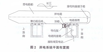
A New Shore Power Cable Winding and Unwinding System
摘要:针对三峡库区大水位差下的岸电电缆收放难的问题,基于滑轮组原理,设计了一套钢丝绳缠绕系统,利用浮箱的浮力驱动传动装置和电缆卷筒运行,在库区水位发生变化时,电缆卷筒可实现对电缆的自动收放,且无需人员值守,绿色安全,为工程的具体设计提供了一种新的可行方案。 1、引言 岸电设施是指船舶在码头停靠期间,由岸上供电系统向船舶提供电力,用以替代船舶燃油发生的设施。随着国内航运的快速发展,船舶排放温室气体量日益增多,岸电设施作为船舶油改电的重要手段,能够降低船舶污染物的排放量,因此得到了快速的发展和应用。 近日来,国内外对于于岸电设施的研究与应用较多,但主要以海港为主,这是因为海港用电需求大,建设难度小,能够取得较好的经济效益;对于水位变化幅度较大的内河区域,面临建设成本高、难度大等问题,如何方便地收放供电电缆,一直没有较好的解决办法。 目前,内河码头的岸电多采用人力拖缆上岸的方式,这种方式效率低、安全隐患大。徐元潮等设计的多级伸缩装置的输缆设备,能够向上提升10m,但不适合水位变化较大的内河区域。2、工程概述 本工程处于三峡库区长江右岸的旧州河河口附近,每个锚泊点由2座系靠船墩组成,可供船舶单艘或者多艘并列停靠。为解决船舶停靠时的供电,拟设备配套的岸电设施,根据《码头船舶岸电设施建设技术规范》(JTS155-2012)要求以及现场调研,船舶受电采用400V/50Hz等级,功率按照400KW设计。受三峡库区调试,锚泊点所在区域水位变化曲线见图1。 锚地区域水位每年6月初到9月底维持在145m,10月初水库开始蓄水,11月初水位升到175m,并维持至翌年12月底,1月初水位开始下降,5月底降落至145m,高水位与低水位落差达30m。此外,由于锚泊点处于库区水域之中,地处偏僻,要求无值守。3、岸电系统总体设计 岸电设施设计的难点在于,在无人值守的条件下如何适应水位的变化,如何准确收放电缆。针对上述要求,结合系靠船墩结构,设计了一套浮箱岸电设施,具体布置见图2。 电缆转接箱从陆域变电站接电,输出至电缆卷筒,电缆卷筒输出给岸电箱,岸电箱置于浮箱上,浮箱置于导向架内,导向架固定于系靠船墩上(见图3)。浮箱可随水位沿导向架上下浮动,通过一套钢丝绳缠绕系统实现电缆的自动收放。4、钢丝绳缠绕系统 钢丝绳缠绕系统主要由滑轮、钢丝绳、联轴板等组成,其原理图见图4。 钢丝绳分为A、B、C、D、E5段,两端分别固定,经绕定滑轮滑轮1、2,以及动滑轮3、4形成滑轮组,动骨轮3和4通过联轴板5相连,固定于浮箱一侧;定滑轮1的转轴与传动装置6的输入轴相连,传动装置6的输出轴与电缆卷筒轴相连,而电缆卷筒上的电缆输出端与岸电箱相连。其中传动装置6实际为一变速器,具有一定的传动比,使得浮箱上下的位移与同时间段内的电缆收放量保持一致。 本系统的原理为:当水面上升时,浮箱随水位沿导向架垂直上升,带动联轴板5向上运动,联轴板5驱使动滑轮4向上运动,整个装置开始运行,动作顺序依次为:浮箱上升→联轴板5上行→动滑轮4顺时针运行→定滑轮2逆时针运行→定滑轮1逆时针运行→传动装置6同向运行→电缆转筒逆时针转动→电缆被卷起收回,从而适应水位的上升,与此同时动滑轮3顺时针运行。 反之,当水位下降时,浮箱随水位沿导向架垂直下降,带动联轴板5向下运动,联轴板5驱使动滑轮3向下运行,整个装置开始运行,动作顺序依次为:浮箱下降→联轴板5下行→动滑轮3逆时针运行→定滑轮1顺时针运行→传动装置6同向运行→电缆转筒顺时针转动→电缆被释放,从而适应水位的下降,与此同时定滑轮2顺时什运行→动滑轮4逆时针运行。 钢丝绳缠绕系统的直接动力源自于浮箱所受的浮力,且理论上浮箱只能上下作直线运行,故方案中设置有专门的导向架,并配合导轨,用以保证浮箱规则运行。 至此,完成了钢丝绳缠绕系统的在岸电收放电缆的逻辑设计,设计中电缆的收缆装置为机械式,通过钢丝绳缠绕系统的作用即可完成输电电缆的收放。该系统能够自适应于不同的水位,且无需人员值守。5、结语 通过对三峡库区锚泊系靠船墩结构和水位的分析,设计了一种浮箱岸电设施,该设施中采用特定的钢丝缠绕系统,利用浮箱浮力驱动其运转,进而带动电缆卷筒工作,从而实现了在不同水位下电缆的准确收放。本系统工作时无需人员值守,绿色安全,为工程的详细设计从理论上提供了一种新的可行方案。 摘自《港口装卸》2020年第6期...