
-
-
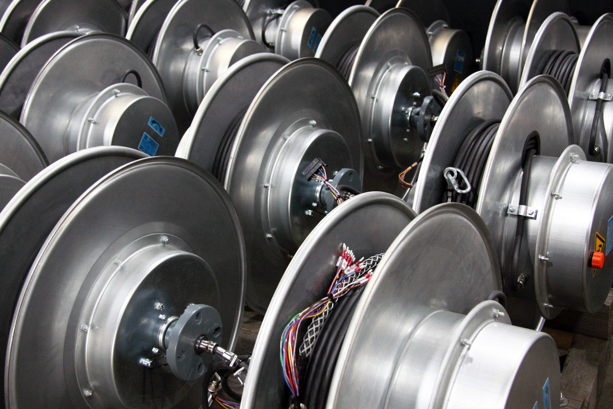
Is it difficult to place cables during mechanical work? Cable reel to help you
With the development of modern industry, the demand for cable equipment is increasing, and cable drums are an important component of these equipment. The function of the cable reel is to roll up and store the cable for easy transportation and use.There are currently many types of cable reels on the market, among which spring type cable reels are a very effective solution. Spring type cable reels are suitable for different types of cables, especially when automatic winding and recycling of cables are required, which is more convenient and fast. The spring structure can automatically roll up and retrieve cables, enabling them to be automatically adjusted, ensuring that the cables are not loose or twisted freely. This makes cable maintenance easier and more effective, while also greatly improving work efficiency.Compared to other types of cable drums, spring type cable drums have more significant advantages. Firstly, the spring type cable reel has a precise control system and adjustable spring force, which can ensure the uniformity and stability of cable sharing on the reel. Secondly, this type of cable reel does not take up too much space and can adapt to different types of site needs. In addition, the spring type drum is also easier to maintain and clean, which can save time and labor costs.Spring type cable reels are suitable for various scenarios, such as factories, docks, commercial buildings, airports, and so on. Whether in construction sites or on-site electrical circuit maintenance, its efficient and stable characteristics help improve work efficiency. Therefore, in scenarios that require extensive use of cables or frequent maintenance of cables, using spring type cable reels is a very wise choice.In summary, spring type cable reels have many advantages and are suitable for most scenarios. The products of Yueyang Kailixin Electric Co., Ltd. not only meet the needs of customers, but also are more advanced in the technical field. If you are looking for efficient, stable, and reliable cable reels, our products will definitely meet your needs....
-
-
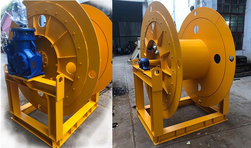
Why choose spring type cable reel?
With the development of modern industry, the demand for cable equipment is increasing, and cable drums are an important component of these equipment. The function of the cable reel is to roll up and store the cable for easy transportation and use.There are currently many types of cable reels on the market, among which spring type cable reels are a very effective solution. Spring type cable reels are suitable for different types of cables, especially when automatic winding and recycling of cables are required, which is more convenient and fast. The spring structure can automatically roll up and retrieve cables, enabling them to be automatically adjusted, ensuring that the cables are not loose or twisted freely. This makes cable maintenance easier and more effective, while also greatly improving work efficiency.Compared to other types of cable drums, spring type cable drums have more significant advantages. Firstly, the spring type cable reel has a precise control system and adjustable spring force, which can ensure the uniformity and stability of cable sharing on the reel. Secondly, this type of cable reel does not take up too much space and can adapt to different types of site needs. In addition, the spring type drum is also easier to maintain and clean, which can save time and labor costs.Spring type cable reels are suitable for various scenarios, such as factories, docks, commercial buildings, airports, and so on. Whether in construction sites or on-site electrical circuit maintenance, its efficient and stable characteristics help improve work efficiency. Therefore, in scenarios that require extensive use of cables or frequent maintenance of cables, using spring type cable reels is a very wise choice.In summary, spring type cable reels have many advantages and are suitable for most scenarios. The products of Yueyang Kailixin Electric Co., Ltd. not only meet the needs of customers, but also are more advanced in the technical field. If you are looking for efficient, stable, and reliable cable reels, our products will definitely meet your needs....
-
-
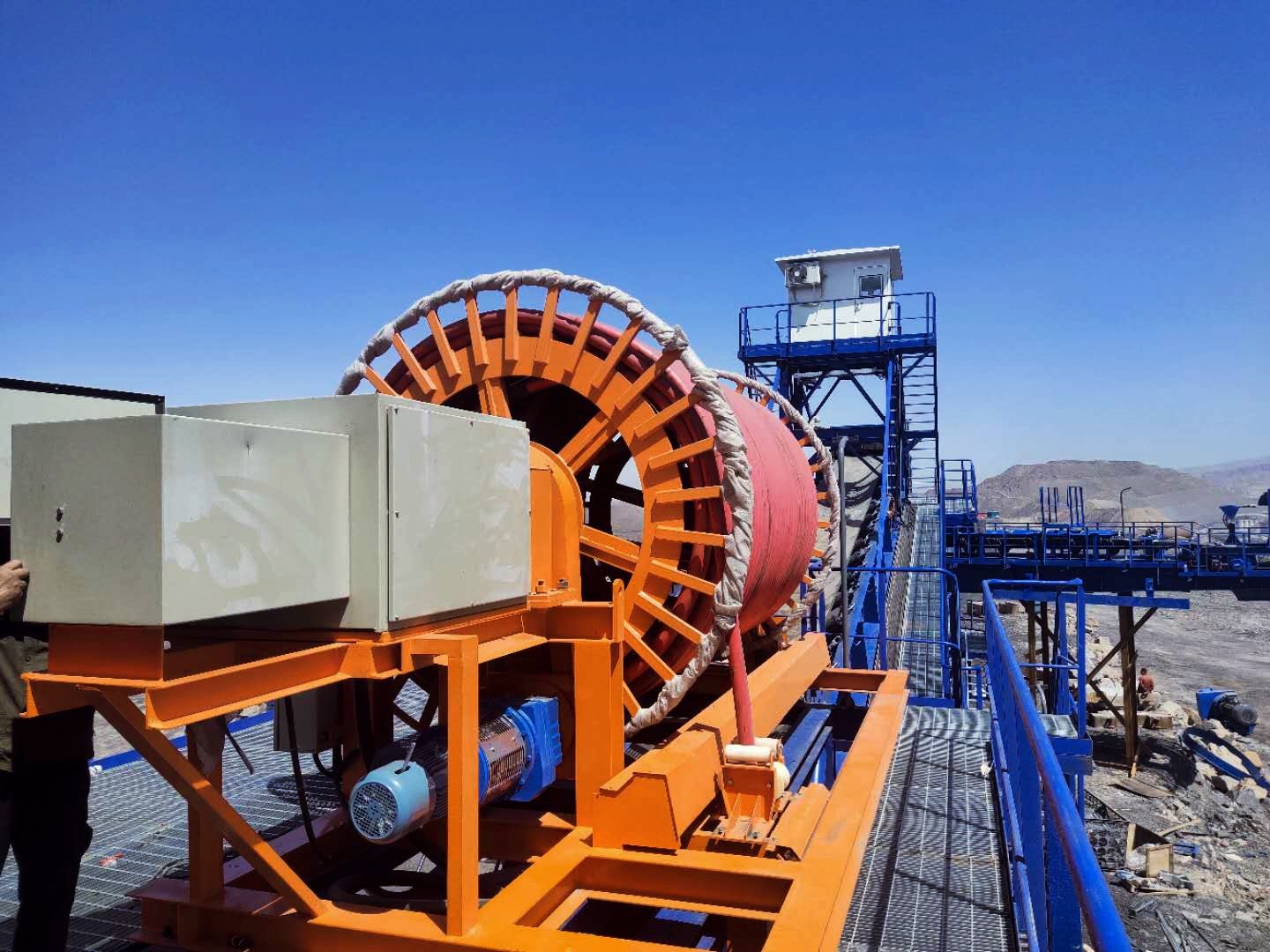
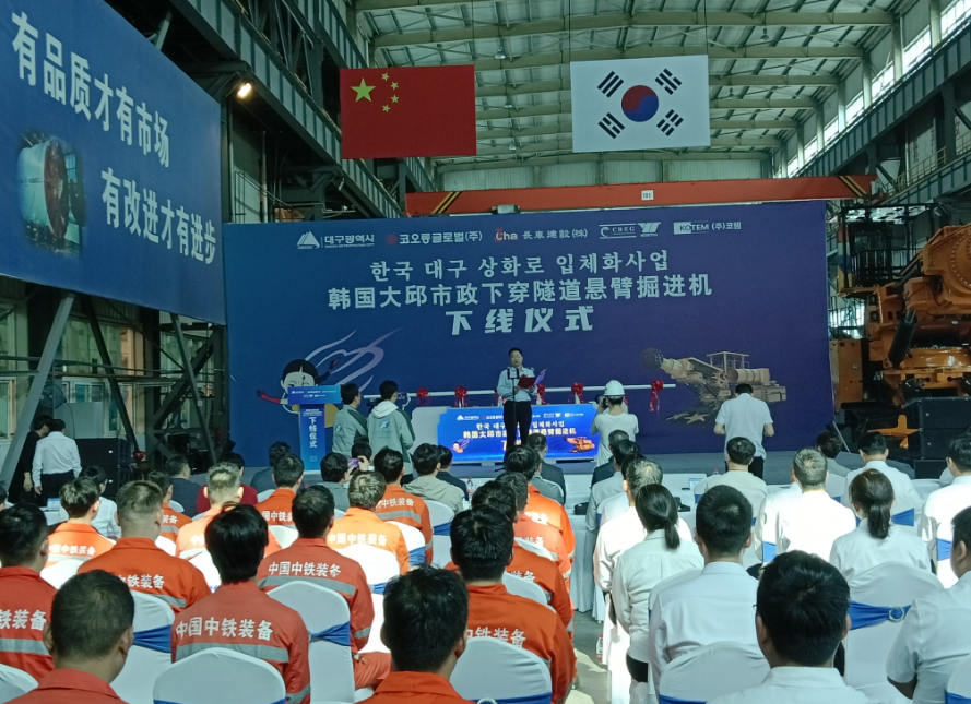
Trithlon Champion! Two of the world's largest longitudinal axis cantilever tunneling machines exported to South Korea for the first time
On April 19th, two "CTR450" cantilever tunneling machines developed by China Railway Equipment Company were successfully put into production in Xinxiang. It is one of the largest longitudinal axis cantilever tunneling machines in the world and will be exported to South Korea for the first time, serving the construction of the Daegu Municipal Underpass Tunnel Project in South Korea. This equipment can withstand the toughest rocks, and the machine's overall weight, cutting rock hardness, and cutting range all set world records, making it one of the all-around champions.Yueyang Kailixin Electric Co., Ltd. has customized hydraulic motor type cable reels for CTR450 cables. The JY series hydraulic motor type cable reels have powerful power, precise control, and efficient energy-saving characteristics, which can adapt to various working conditions and have low noise during operation without excessive noise pollution. These advantages have won the trust of customers and also extended the service life of the drum.In the future, these cantilever tunneling machines will become important tools for tunnel construction and will be widely used in many tunnel construction projects. As a leader in the domestic cable reel industry, Yueyang Kailixin Electric Co., Ltd. will be committed to providing customers with higher quality products and solutions....
-
-
Utility Model Patent: A Winding Device with A Pneumatic Brake
AbstractA winding device with pneumatic controller includes reel assembly mechanism, power reduction mechanism, rotary joint assembly mechanism, pneumatic control braking mechanism, torque limit and travel limit protection mechanism, pneumatic control components and electrical control mechanism. The utility model is an electric winding device which can effectively compress the product size by adjusting the air pressure and adjusting the braking torque. According to the working characteristics of the shield machine, when the winding device retracts the cable, the motor is powered on and drives the reel to drag the water pipe from the ground into the reel. When the winding device conducts cable laying, the motor loses power, and the water pipe is dragged out from the reel to the effective distance by external force. At this time, the air pressure can be adjusted by 0-0.8MPa, and the friction torque of the brake can be adjusted to easily drag the water pipe out. The utility model greatly meets the demand of the shield machine market, can comprehensively replace similar foreign products, and has the advantage that it is cost-effective. Technical FieldThe utility model relates to the winding device for a shield machine, in particular to the winding device with a pneumatic brake. Background ArtWith the continuously growing demand and high-end of China's mechanical equipment industry, so far, China's urban subway projects have an increasing demand for shield machines. Domestic shield machines have broken through foreign monopoly and most of them have been localized. Corresponding domestic manufacturers also have substitutes of the supporting water pipe drum. However, according to the actual working conditions of the shield machine, the water pipe drum with pneumatic control cable laying is still from foreign countries. The domestic manufacturers use the hysteresis water pipe drum instead. When the diameter of the water pipe is too large and the coiling length is too long, the coiling torque of the hysteresis water pipe drum is often insufficient. The product size is too large, which may be easily limited by the installation space of shield machine, which restricts the development of products. ContentsThe utility model aims to provide a winding device with a pneumatic brake to solve the problems in the background art.The contents of the utility model is realized through the following technical solutions:A winding device with a pneumatic brake includes reel assembly mechanism, power reduction mechanism, rotary joint assembly mechanism, pneumatic control braking mechanism, torque limit and travel limit protection mechanism, pneumatic control components and electrical control mechanism. The mentioned reel assembly mechanism is connected with the rotary joint assembly mechanism. The mentioned power reduction mechanism is connected with the pneumatic control braking mechanism.The reel assembly mechanism comprises a reel outer ring, a reel inner ring, a reel drum, a drum support rod, a water pipe, a reel connecting flange, and the mentioned reel drum. The mentioned reel assembly mechanism is a cable storage device for winding the water pipe into the reel.The power reduction mechanism comprises a main shaft, a single-row tapered roller bearing, a front end cover, a reduction gearbox assembly, a big bevel gear, a large bevel gear fixing flange, a three-phase AC asynchronous motor, a connecting flange, a planetary reducer, a gear gasket, a small bevel gear, a bearing transparent cover II, a shaft retaining ring II and a shaft sleeve. Because many shield machines are limited in the width direction of the drum, the selection of appropriate reduction ratio bevel gear in the power reduction mechanism can reduce the width of the reduction box.The mentioned rotary joint assembly mechanism comprises a shaft retaining ring I, a right-angle joint, a deep groove ball bearing, a bearing transparent cover I, a bearing outer retainer ring, a rotary joint, a shaft seal ring, a hole retaining ring and steel pipe outer thread welding socket. When the water pipe drum works, the water pipe needs to be wound, and the water outlet of the drum must be connected into the equipment. The mentioned rotary joint assembly mechanism is a device to ensure the rotary conversion of the connecting part of the water pipe.The mentioned pneumatic control braking mechanism comprises a friction wheel assembly and a pneumatic brake. The mentioned torque limit and travel limit protection mechanism comprises a main shaft sprocket, a travel limit switch and a torque limiter. In the pneumatic control braking mechanism, since the motor does not have an electromagnetic brake, a pneumatic control brake is installed between the motor output shaft and the planetary reducer. By manually adjusting the air pressure of 0-0.8MPa, the brake torque can be adjusted to the appropriate hinder torque, and the water pipe can be dragged out of the reel slowly by external force, which can ensure that the water pipe will not fall off due to gravity.The pneumatic control components and the electrical control mechanism include an air filter with a pressure gauge, air pipes, a precision pressure regulating valve, a two-position three-way solenoid valve, a three-way quick connector, and an electric control box. For the mentioned torque limit and travel limit protection mechanism, when the winding device is winding the cable, the water pipe is inadvertently blocked by obstacles and cannot be winded into the reel. At this time, the excessive torque will break the water pipe. Therefore, a torque limiter is installed to ensure that the torque limiter slips and the appropriate output torque will not break the water pipe. When the water pipe reaches the end of the stroke, there should be more than one safety turn to set the travel limit. At this time, the travel limit switch sends a signal to cut off the power supply of the crane, so that the water pipe is not completely pulled out of the reel.The front end of the friction wheel assembly is an output shaft inserted into the planetary reducer, the lower end of the output shaft of the planetary reducer is connected with a small bevel gear, the large bevel gear is connected with the main shaft through a key, the front and rear ends of the main shaft are equipped with reel connecting flanges, the reel and reel connecting flanges are connected through bolts, the reel is equipped with a rotary joint, and one end of the reel is connected with the water pipe. The pneumatic control components and the electric control mechanism are the actuator and the operating mechanism of the winding device.The utility model has the following beneficial effects:The utility model is a winding device with a pneumatic brake. It is an electric winding device which can effectively compress the product size by adjusting the air pressure and adjusting the braking torque. According to the working characteristics of the shield machine, when the winding device retracts the cable, the motor is powered on and drives the reel to drag the water pipe from the ground into the reel. When the winding device conducts cable laying, the motor loses power, and the water pipe is dragged out to the effective distance by external force. At this time, the air pressure can be adjusted by 0-0.8MPa, and the friction torque of the brake can be adjusted to easily drag the water pipe out. The utility model greatly meets the demand of the shield machine market, can comprehensively replace similar foreign products, and has the advantage that it is cost-effective....
-
-
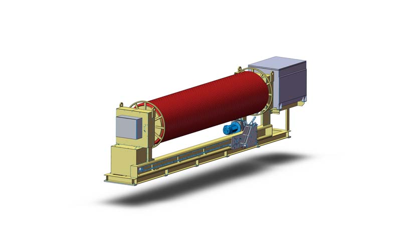
Long-distance Drum Type Cable Winding Device
Abstract:The utility model relates to a cable winding device, in particular to a long-distance drum type cable winding device. The long-distance drum type cable winding device is mainly composed of a winding drum and a cable guider, which are connected through a sprocket and a chain. One end of the drum is provided with a slip ring box, and the other end is provided with a motor and a deceleration system. It is applicable to coiling ultra-long-distance cables. When the machine moves and walks, the power supply of the ground system is supplied to the power supply system on the machine, and the cable arrangement mechanism is installed to make the cables arranged neatly during cable retracting. The design of the cable arrangement mechanism of the long-distance cable drum has been optimized that hydraulic coupling deceleration system is used, which can solve the power supply problem of large-scale mobile electric equipment. It has the characteristics: easy to operate; safe and reliable; high degree of automation, etc. Technical Field:The utility model relates to a cable winding device, in particular to a long-distance drum type cable winding device. Background Art:With the rapid development of the mechanical device industry in China, large-scale mobile power supply equipment is more and more widely used. At this stage, the cable winding and unwinding equipment supporting such equipment mainly relies on import, which is not only expensive, but also can not fully meet the performance and working condition requirements of domestic equipment. Contents:In order to solve the shortcomings in the existing technology mentioned above, the object of the invention is to provide a long-distance drum type cable winding device for a mobile system. It can directly connect the power supply end with the mobile system. The cable will be automatically wound and unwound with the movement of the terminal. It cooperates with the worm gear deceleration system to effectively prevent the cable from breaking. It has the characteristics: easy to operate; safe and reliable; high degree of automation, etc.In order to achieve the invention purpose mentioned above, the technology of the invention is realized in the following manner: The long-distance drum type cable winding device is mainly composed of a winding drum and a cable guider, which are connected through a sprocket and a chain. One end of the drum is provided with a slip ring box, and the other end is provided with a motor and a deceleration system. The motor adopts Y-series three-phase asynchronous motor, and the reduction system is composed of worm gear, worm, hydraulic coupler and sprocket with self-locking. The slip ring box is provided with a carbon brush, a slip ring and an insulating ring, and a pin shaft is installed between the cable guider and sprocket.The motor is powered on to drive the worm and worm gear to rotate. The worm gear is installed on the reel shaft and can rotate freely. Two friction discs are installed on both sides of the worm gear and fixed on the reel shaft through keys. During rotation, oil film can be generated between the worm gear and them to transmit torque. Motor torque is transmitted to the reel shaft through the hydraulic coupling combined with the worm gear reduction system. The hydraulic coupler is composed of a friction disc, a compressed spring, a spring holding disc and a torque adjusting nut. The output torque can reach zero and maximum by adjusting the compression of the spring on the hydraulic clutch.During cable retracting, the motor is powered on, and the torque output unit drives the drum to coil the cable. At this time, the hydraulic coupler slips to synchronize the cable retracting speed with the running speed of the crane.During cable laying, the motor is powered off, and the cable traction drum rotates in the opposite direction to lay the cable. At this time, the worm gear deceleration system has self-locking performance, and the hydraulic coupler slips, so that the cable laying speed of the drum is synchronized with the running speed of the crane.When the crane stops, the motor is powered off. At this time, the worm gear deceleration system has self-locking performance, and the hydraulic coupler can also play the role of braking, which can effectively prevent the cable from falling due to gravity.Between the drum slip ring boxes, a group of sprockets and tapered reversing gears are led out from the reel shaft and driven by chains as the power of the cable guider. By lengthening the pin shaft of a sprocket and inserting it into the cable guider, the chain will drive the cable guider to move horizontally left and right for uniform cable laying.When the drum retracts the cable, the cable guider arranges the cable in the forward direction. When the cable guider reaches the end point, the pin shaft on the chain rotates and reverses around the sprocket, which changes the moving direction of the cable guider and makes the cable guider arrange the cable in the reverse direction.When the drum unwinds the cable, the cable guider arranges the cable synchronously and reversely. The cable arrangement when the cable guider reaches the end is the same as that when the cable is retracted.Through the function of cable guider, the cables with ultra-long distance can be arranged neatly to avoid the random arrangement of cables on the drum. Beneficial effect:By adopting the structure mentioned above, the utility model overcomes the defect that similar foreign equipment is easy to break the cable. The design of the cable arrangement mechanism of the on-board large-scale cable drum has been optimized that hydraulic coupling deceleration system is used, which can solve the power supply problem of large-scale mobile electric equipment. The utility model has the advantages: easy and reliable operation; compact structure; saving space....
-
-
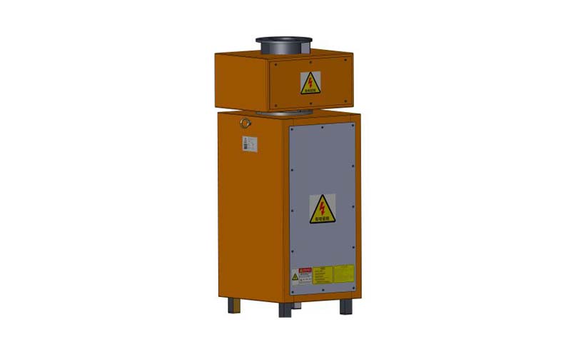
A Multi-functional Central Collector Device
Abstract:The multi-functional central collector device is mainly composed of: an infinite rotating optical fiber coupler, which is connected with a slip ring hollow shaft and an integrated slip ring through a bearing, then connected with a power ring bar, a copper slip ring and a power ring carbon brush through a transmission seat, and then connected with a lower bearing seat and a lower hollow shaft through a bearing. Through the system, the device can integrate the power supply signal, common control signal and optical fiber communication signal together to provide stable and reliable transmission of signals for rotating equipment. The device adopts the form of under drive and transmits the current signal and control signal through the rotation of the slip ring, which effectively solves the problem of cable knotting and entangling after the rotating equipment transmits signals through the hard-wired cables. It has stable performance and is easy to maintain, and can be widely manufactured and used. Technical Field:The utility model belongs to the technical field of electronic converters, in particular to a multi-functional central collector device for supplying power to large-scale mobile electric equipment such as stacking and pick machine. Background Art:With the rapid development of the mechanical device industry in China, large-scale mobile power supply equipment is more and more widely used. Moreover, the intelligent means of equipment are becoming higher and higher, and the accuracy of equipment control is also becoming higher and higher, including all kinds of high-precision and high-sensitivity detection signals, video, network, audio and other signals. Therefore, the requirements for transmission become stricter. Optical fiber is needed on many occasions, but it is well known that optical fiber can not be folded, which makes the rotating transmission of signals need specific equipment. At this stage, the rotating power supply equipment supporting such equipment mainly relies on imports, which is not only expensive, but also can not fully meet the performance and working condition requirements of domestic equipment.How to integrate the power supply signal, common control signal and optical fiber communication signal together to provide stable and reliable transmission of signals for rotating equipment. Providing a stable multi-functional central collector device has become an urgent problem to be solved. Contents of Utility Model:The utility model aims to solve the above shortcomings and provide a multi-functional central collector with stable performance.This technical solutions for achieving the objectives mentioned above are:The utility model provides a multi-functional central collector device, which is mainly composed of an infinite rotating optical fiber coupler, which is connected with a slip ring hollow shaft and an integrated slip ring through a bearing, then connected with a power ring bar, a copper slip ring and a power ring carbon brush through a transmission seat, and then connected with a lower bearing seat and a lower hollow shaft through a bearing.The utility model adopts the structure of under drive. The rotary support of the main engine drives the lower bearing seat of the central collector to rotate. Since the lower bearing seat is connected with the copper ring, the power slip ring, collector slip ring and infinite rotating optical fiber coupler also rotate with the rotary support, realizing the relative rotation of the slip ring and the housing. The rotary support of the main engine drives the lower bearing seat of the central collector to rotate. Since the lower bearing seat is connected with the copper ring, the power slip ring, collector slip ring and infinite rotating optical fiber coupler also rotate with the rotary support, realizing the 360° free rotation of the collector. High-current conductive copper slip ring and power ring carbon brush are adopted. Outside the utility model of multi-functional central collector device, a plastic spraying electrical element cabinet with high protection grade is adopted, so that the internal live parts are completely electrically isolated from the outside.The power and control signals come from the transformer box, pass through the cable drum, enter the incoming protective cover of the central collector, and then connect to the collector slip ring contact or the wiring terminal. Then, they are transmitted to the wiring terminal of the outgoing line by the friction contact between the conductive slip ring and the carbon brush, and then transmitted to the main control room by cable, completing the whole set of balanced transmission of current signals and control signals.Beneficial effects: Through the system, the device can integrate the power supply signal, common control signal and optical fiber communication signal together to provide stable and reliable transmission of signals for rotating equipment. The device effectively solves the problem of cable knotting and entangling after the rotating equipment transmits signals through the hard-wired cables. It has excellent conduction characteristics and good electrical isolation performance. Modular components are adopted, so that it is easy to maintain and can be widely manufactured and used. ...